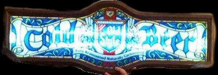
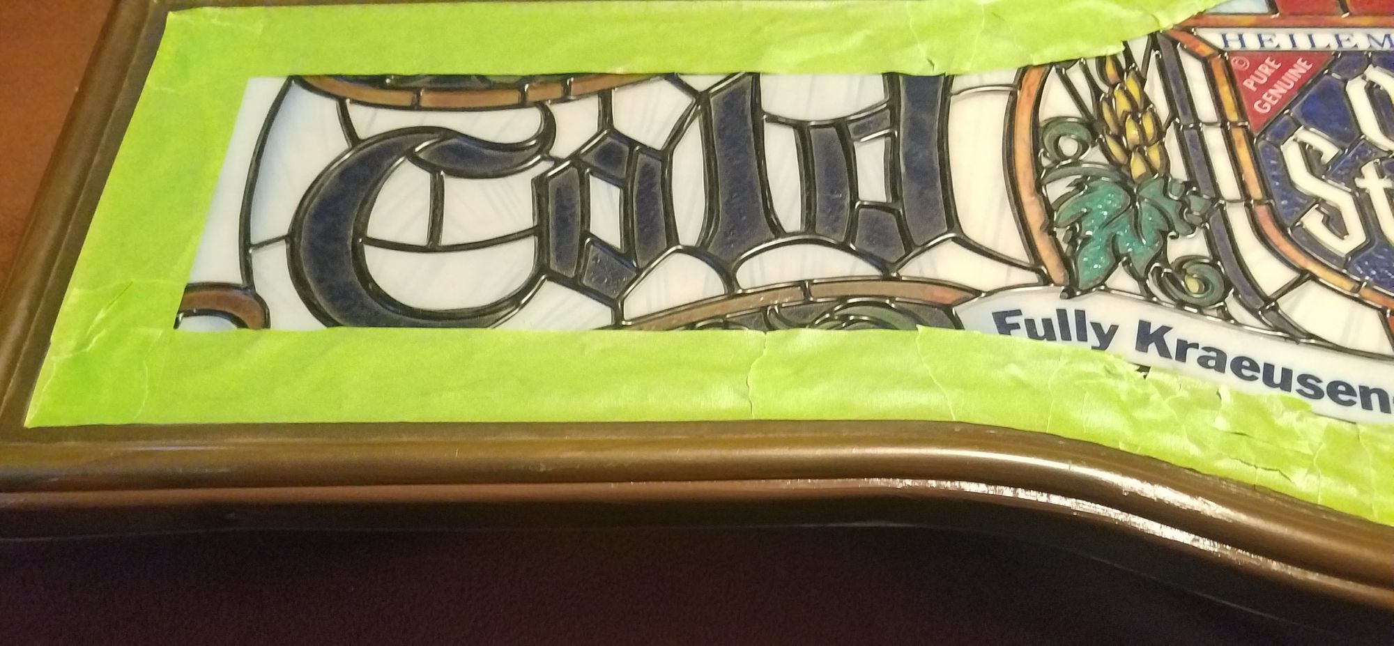
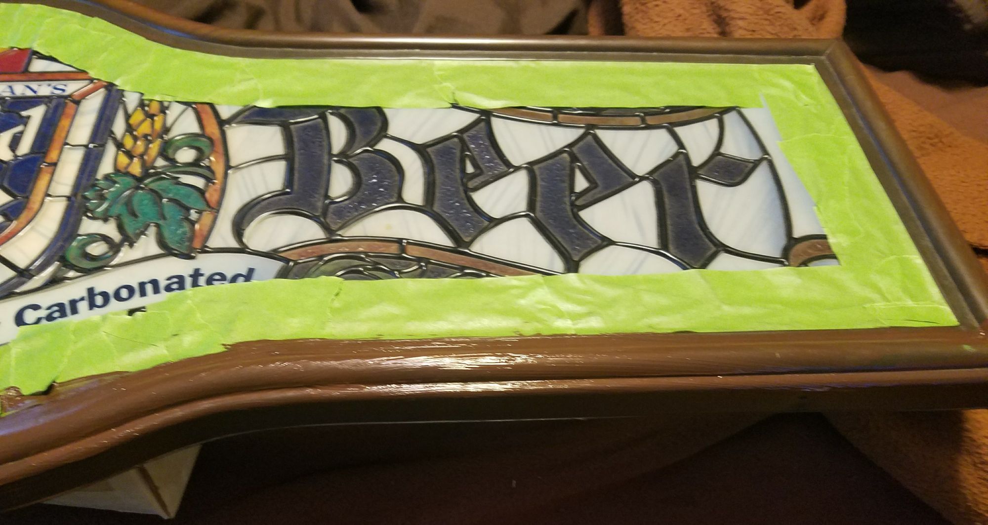
This is a project that I completed a while ago as a gift to give to a friend. Unfortunately some pictures were lost along the way so I'll try to be as detailed as I can in describing what was done. The bar sign was picked up from a local flea market for a few bucks. The original lamp still worked but my immediate intention was to replace the old, and HOT, tubes with LED strips. Due to some past shipping shenanigans ordering parts for another project, I already had an extra set of LED strips and controller sitting around so I just needed something to provide them power and a PWM signal for the brightness control. Since a Raspberry Pi Zero W has 2 configurable PWM outputs, a bunch of GPIO pins for physical controls, and a very small foot, I decided to go with that since it would also give me an opportunity to do a small software project. I also needed to repair some cracks and gaps in the "frame" of the front panel. My original idea was to try and match the plastic color with a brown ABS slurry, but that proved to be a fruitless effort and due to some other scuffs and scratching I ended up repainting the entire "frame" of the front panel. Filling in the framing with new plastic was pretty easy. I just had to using some masking tape to create a flat surface for the fill, mix together some ABS plastic (I used some cheap and readily available 3D printer filament) with some acetone to make the slurry, and filled in the blanks. Once the ABS slurry tried I just had to peel off that masking tape and then put some new masking tape over the front so I could paint the frame without dripping or smearing onto the "glass".
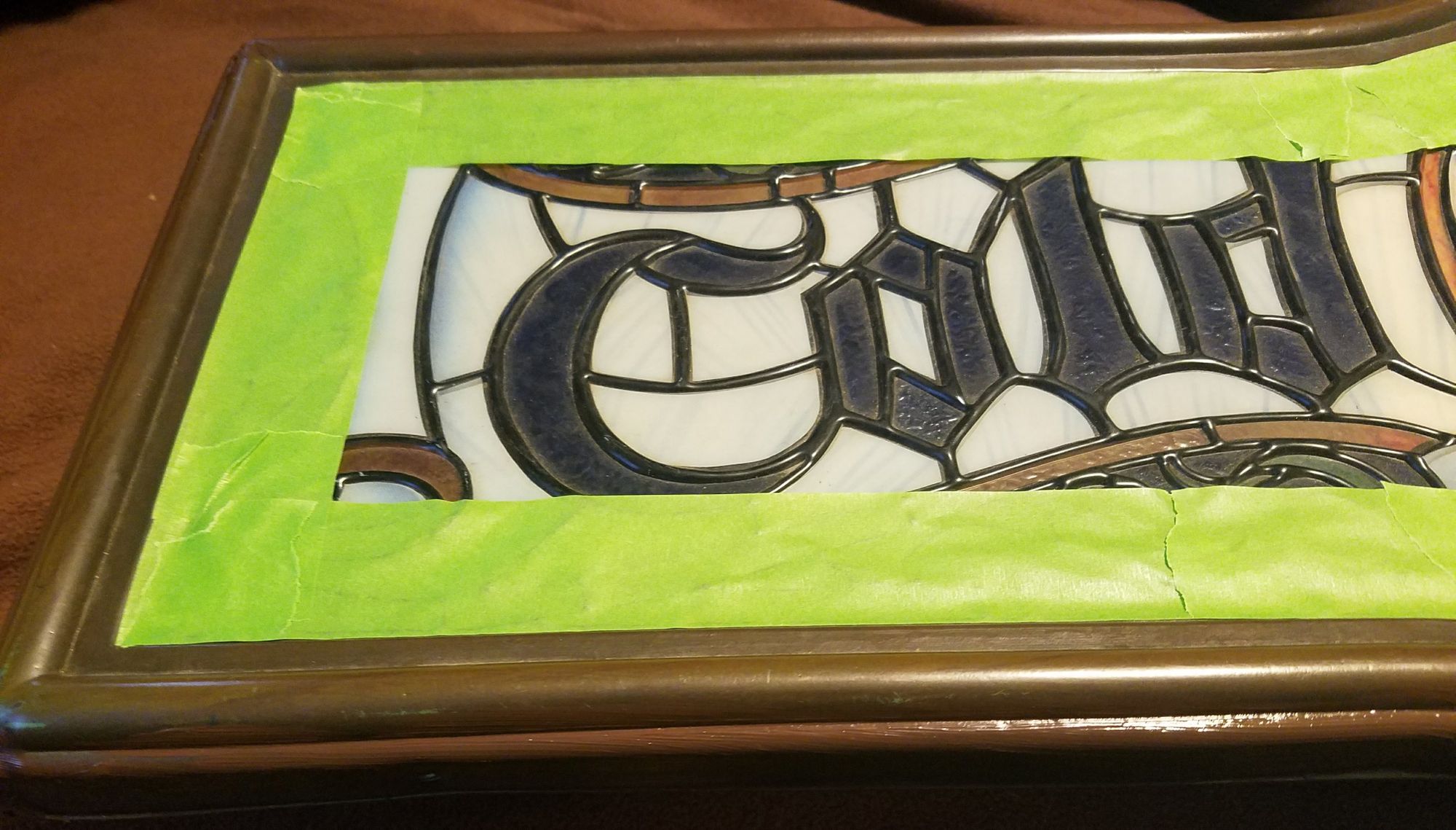
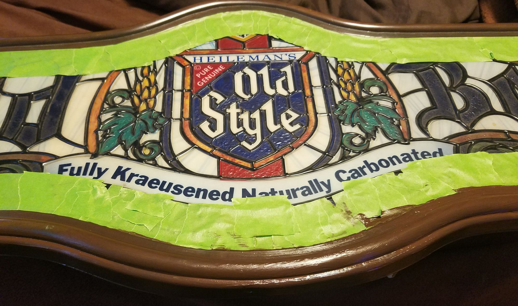
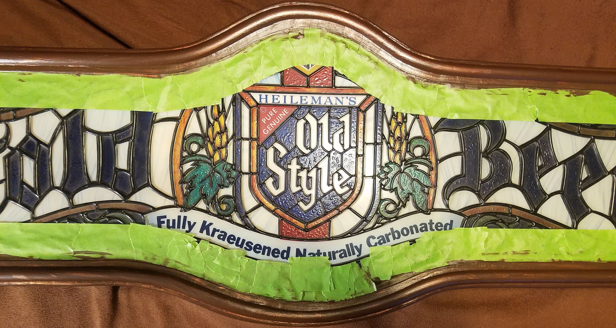
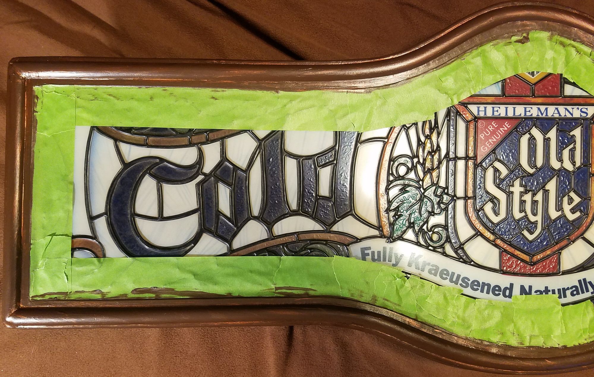
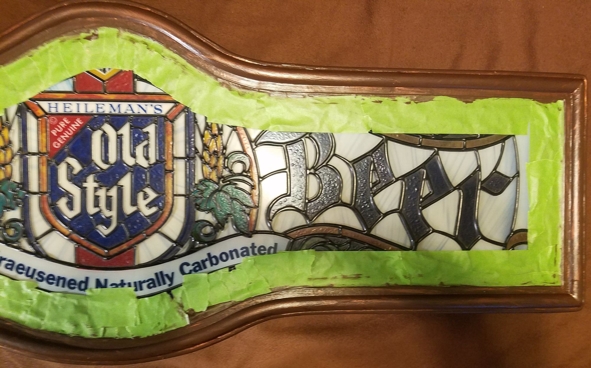
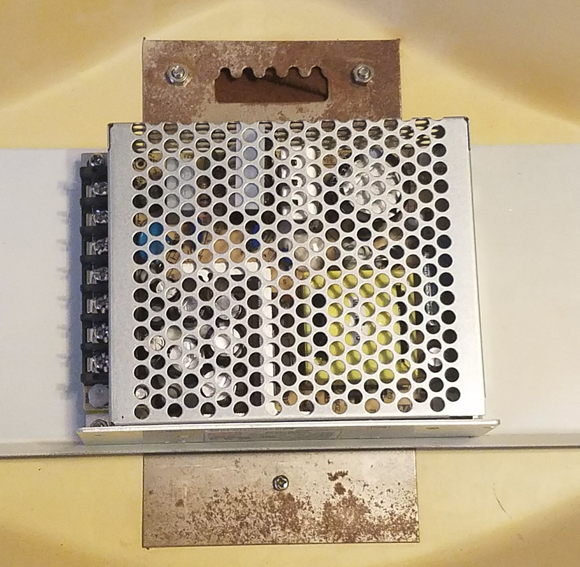
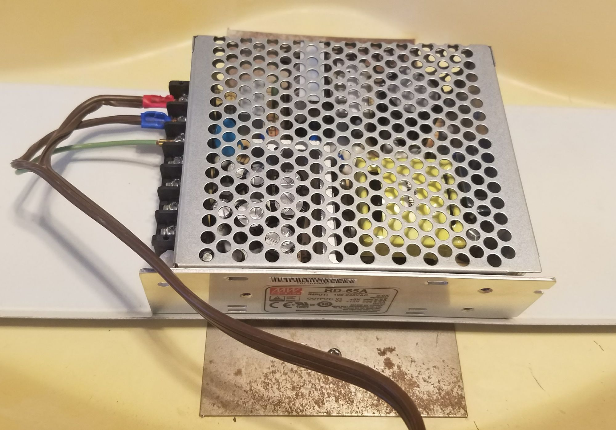
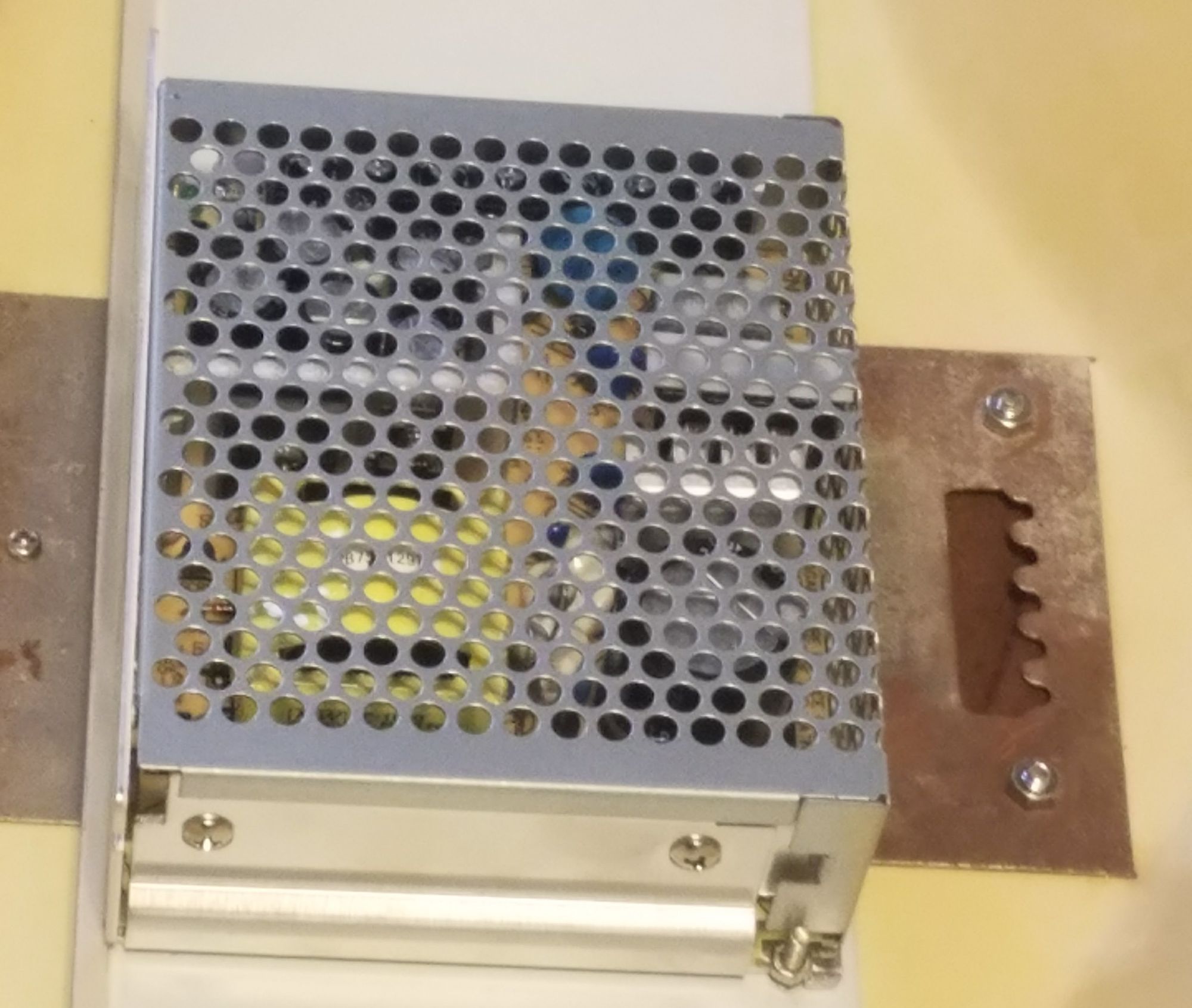
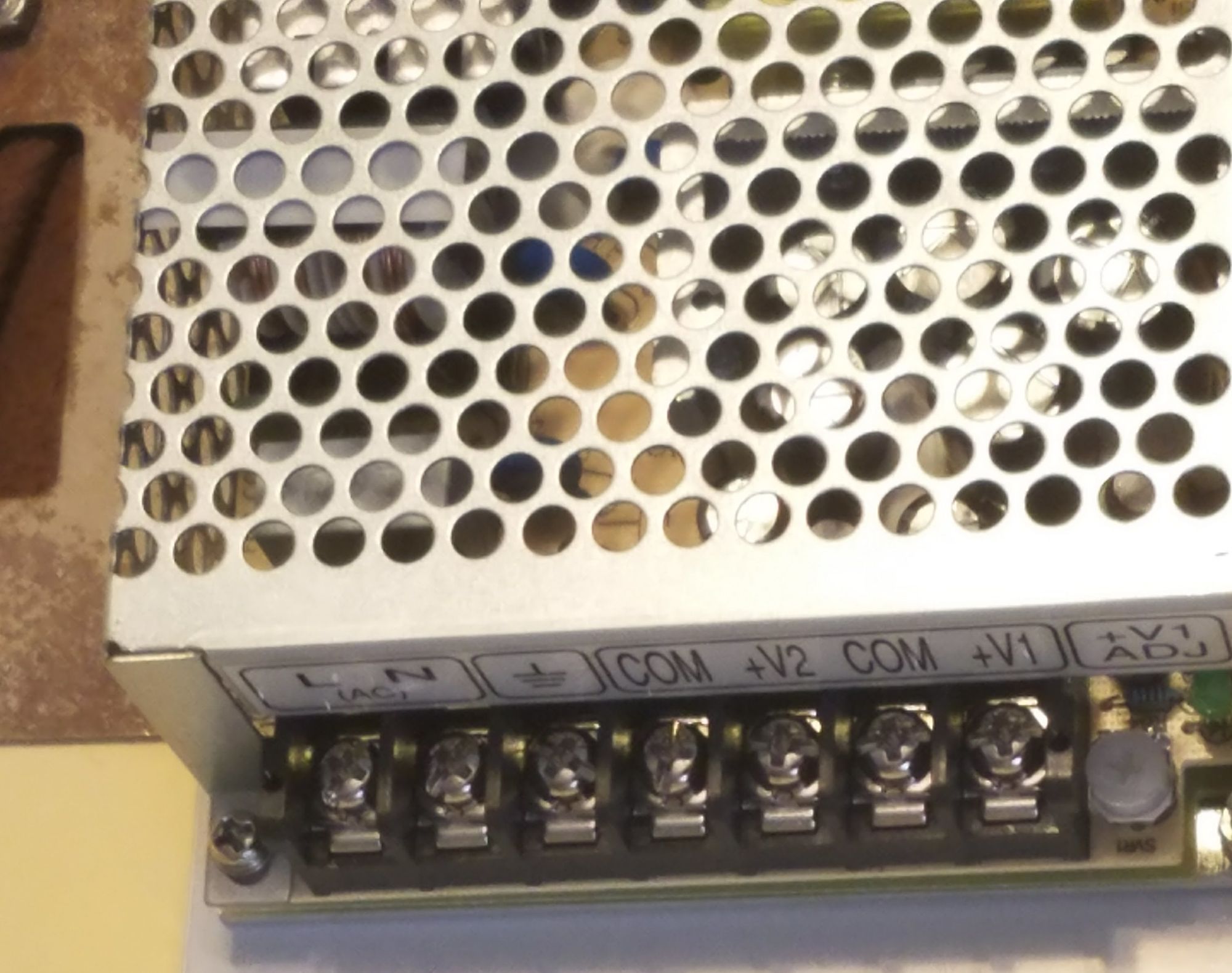
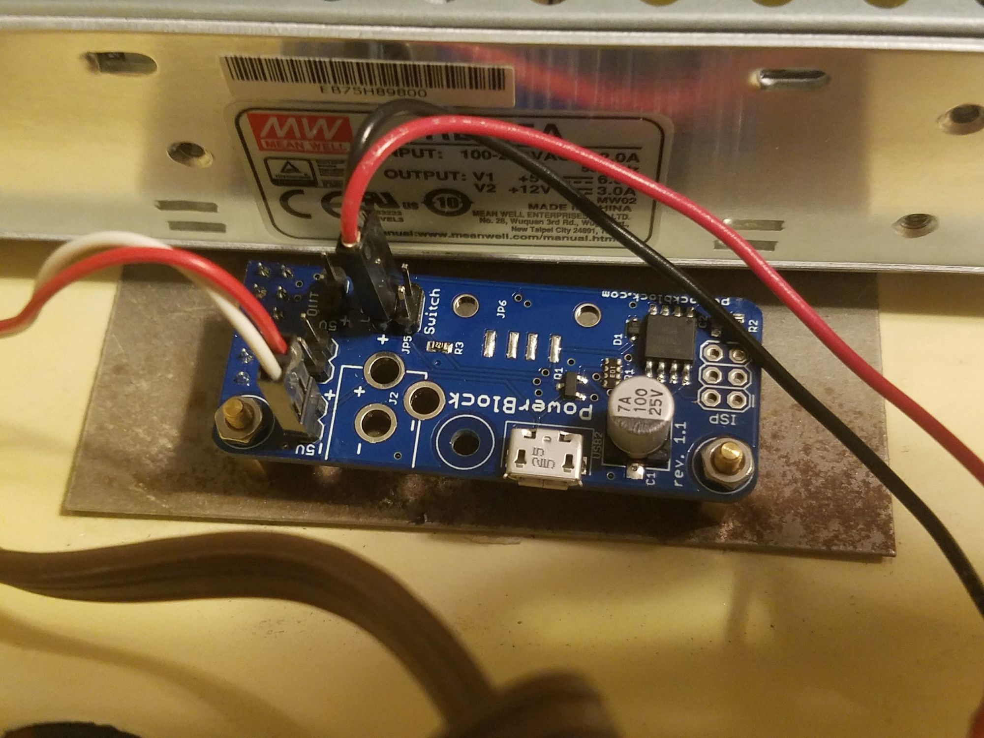
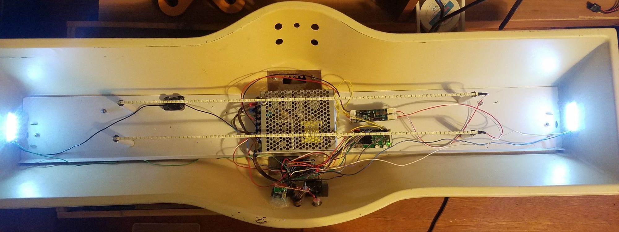
I applied a dark brown base coat and then stylized it with some metallic bronze to approximate the original look. Overall, I'm very happy with the results. Next I needed to install a new power supply. Supplying the Raspberry Pi with 5V of DC power is pretty cheap and easy but the controller for the LED strips needed 12V DC in order to operate. The dual supply PSU I ended up buying is probably a bit overkill but its dimensions were perfect for tucking behind the LED strips and an extra available ampere or 2 isn't going to break anything. This unit also had tapped screw holes on the underside which made mounting it to the internal metal plate that used to hold the lamp transformer, while also serving as the wall hanger, very easy after drilling a couple new screw holes. As you can see in the picture below the original AC wall plug had a couple new terminals crimped on and was attached at the appropriate input points.
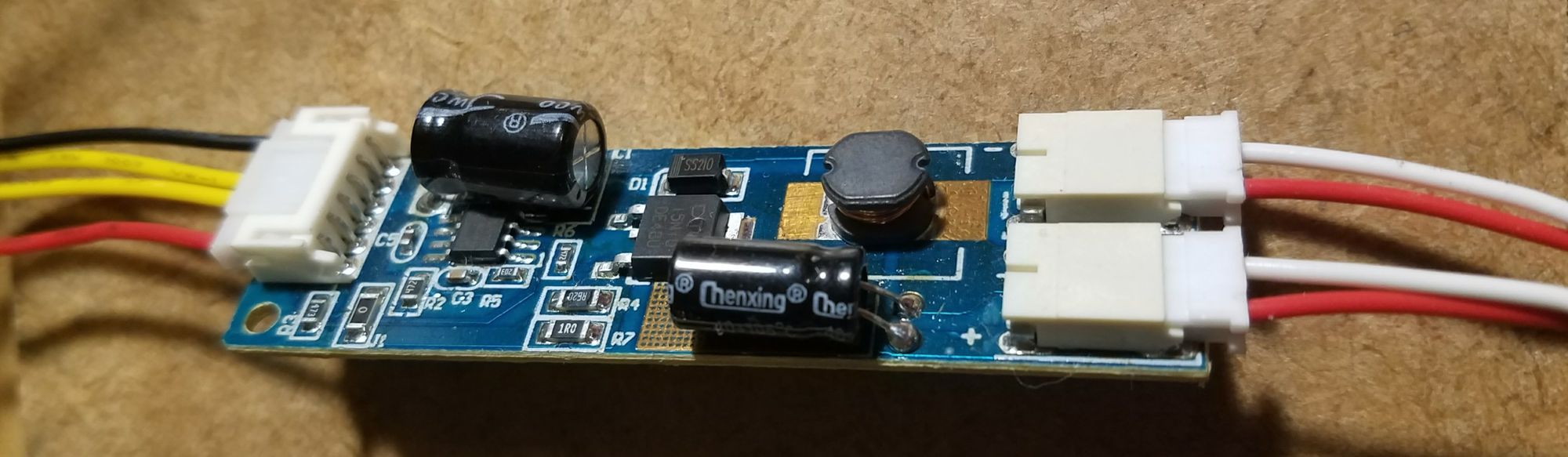
With the base work on the fixture complete it was time to move onto developing the software to control the LED strips. The datasheet for the LED driver board gave me a basic idea of how to interface with the brightness control but I still needed to do some experimentation with how to step through the voltage range. The board accepts a control voltage on one input for turning the lamp on and a variable range on the other input for controlling the brightness. The driver boards 12V inputs were connected to a bench supply for testing and the Pi Zero W was connected to the 2 control inputs.

Since the Pi was going to be embedded into the fixture I also board an add on power control board for the Pi itself that has its own power LED output, switch input for powering the Pi on and off, and outputs to connect to the Pi's GPIO so that it can be configured to do a graceful shutdown when the power button or switch is activated.
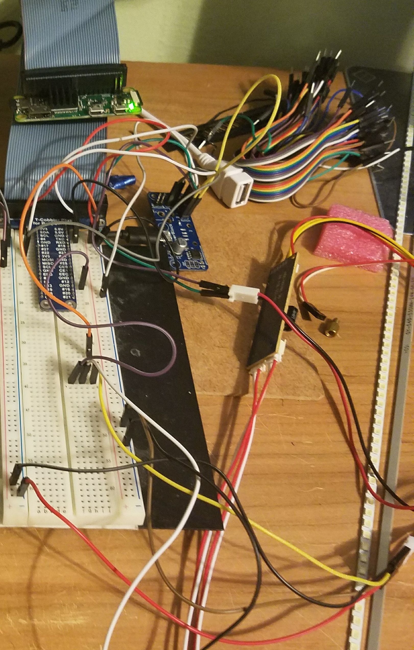
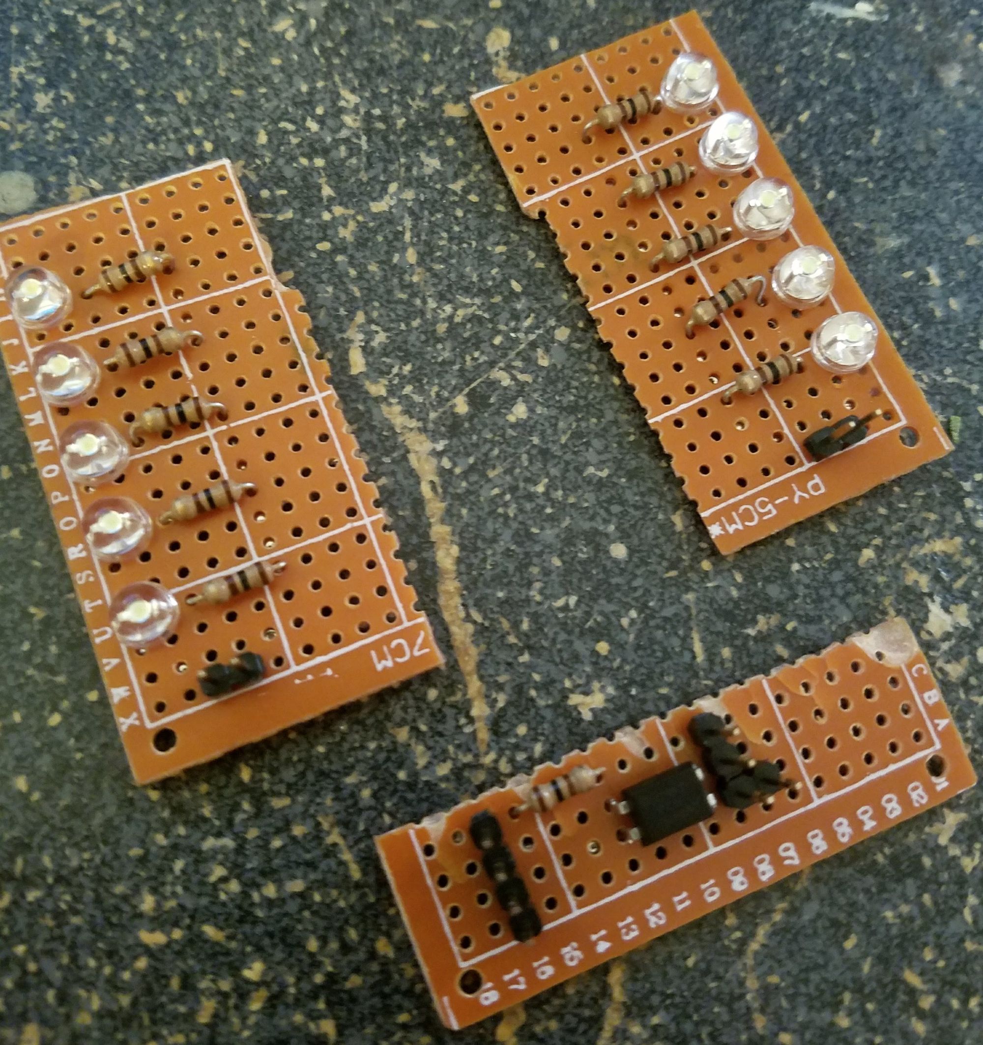
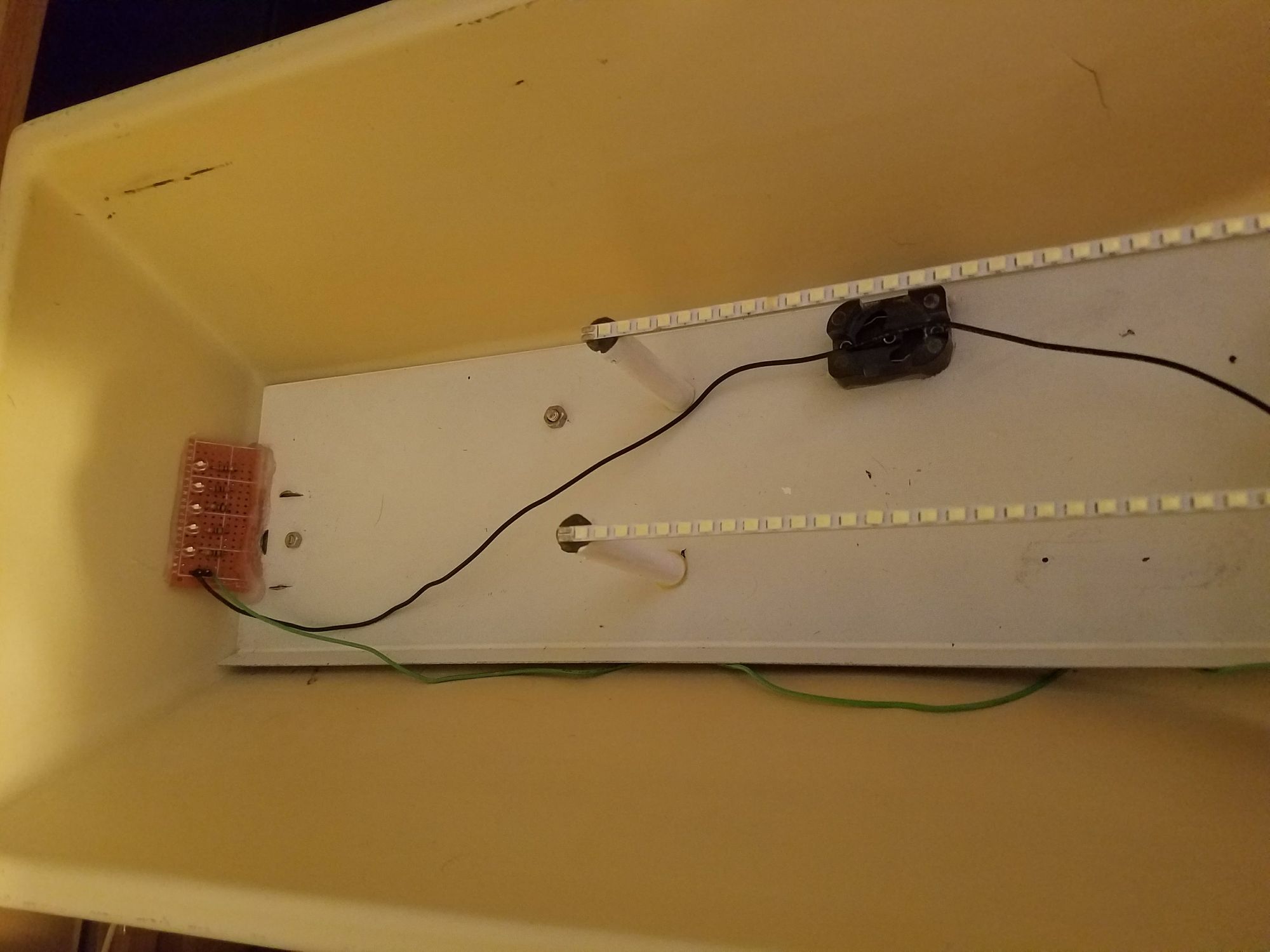
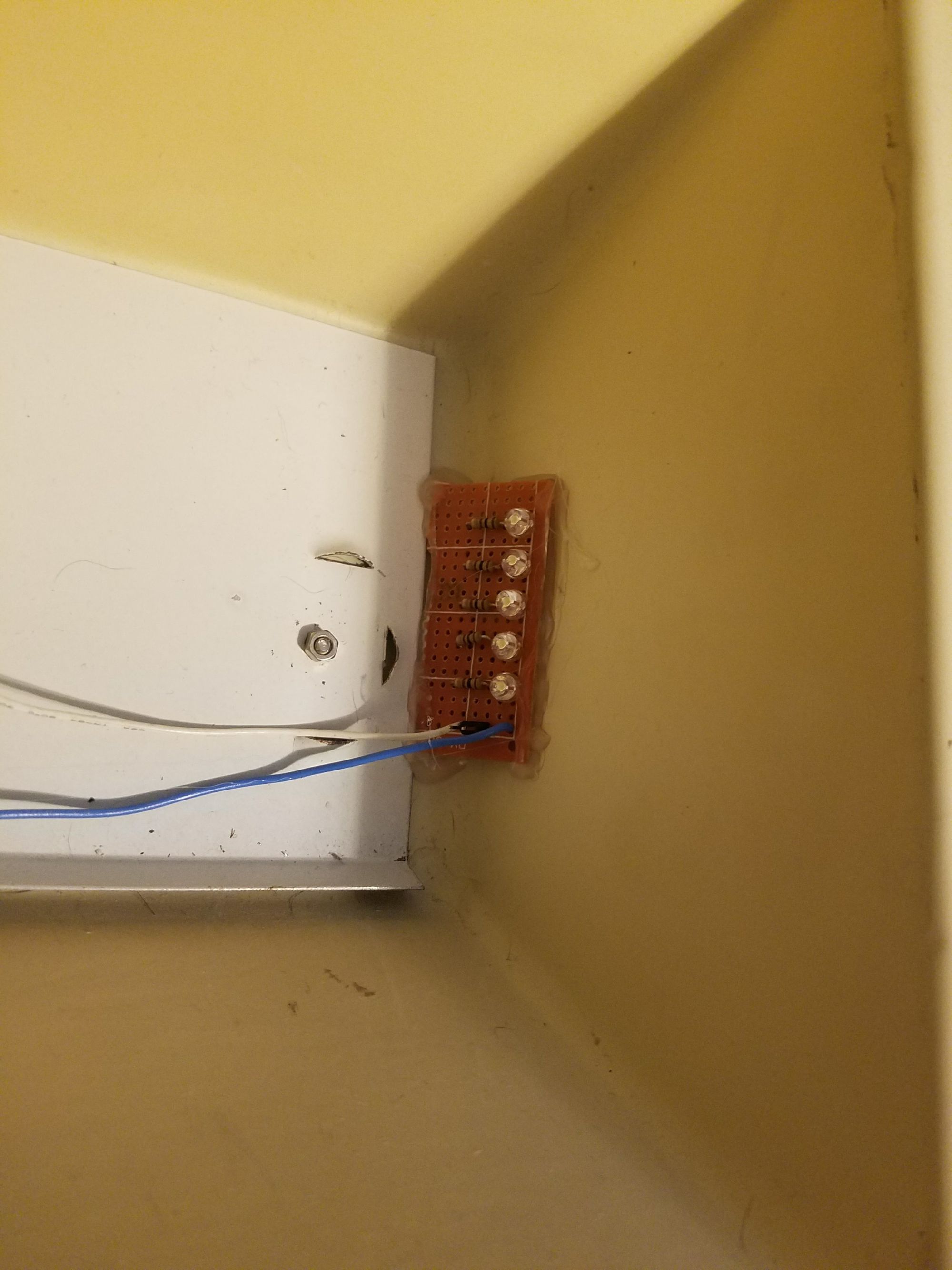
I had originally intended just to had the 2 LED strips inside the sign, but the overall length of the strips prevented them from properly lighting up the corners of the sign as I intended so I quickly designed and built a couple of LED light modules and a basic control board to fix this issue. Since I was powering 10 LEDs I used an octocoupler to separate power, the 5V output from the PSU, and control into 2 independant signals. This also added another feature to the sign. Since these could be controlled independently of the main strips I was able to add the option of only lighting up the side lights as an additional mode. Although this did made the software component a bit more complicated as I now needed to encode more states. A rotary encoder was hooked up to the Pi to cycle through the available states defined in the software.
Once experimentation was over it was time to finish mounting the rest of the components into the light. A few additional holes were drilled into the back of the fixture in order to attach brass stand offs for the components.
The LED side panel lights were just glued in place at an angle since there's a pretty low change they will need to be taken out again at some point. The fixtures controls, the rotary encoder and power switch, as well as the power LED and a USB serial interface were mounted through some existing holes, presumably vents for the old lamp, so that they come out of the curved back of the light. This allows for easy access while also hiding them from view. The USB serial device was added in order to provide an easy way to access a terminal interface on the Pi without removing it from the light or if it is not connected to a WIFI network. The LED strips were mounted on a few wooden dowel posts that were also painted white.

With all the physical work completed, the only things left were deploying the scripts and configuring a SystemD startup service to run the Python script to control the various aspects of the light. This service (pwm_rotary_light.service), the final script (pwm_rotary_light.py), and a few smaller scripts demonstrating some of the functions independently are available on a Github page.