Playing 78RPM records and monophonic vinyl records pressing from the mid-1960s-ish and earlier on modern stereo turntables presents some issues. It should be well known already that 78RPM records require a different size of stylus, 3mil vs 0.7mil, compared to vinyl records. Playing back the previously mentioned records, however, also present another lesser known problem. Unlike stereo vinyl records and later mono vinyl releases pressed on a stereo record lathe, these records have grooves cut in a different manner from stereo record. These monophonic records have groves that are recorded in the lateral direction only on one side of the groove, whereas stereophonic records have sound etched into both sides of the groove. Stereo needles and cartridges are still able to read these records, but the extra motion from the dual channel nature of the setup adds noise to the signal. One solution to this is to have a completely separate "true mono" cartridge. However, many that claim to be mono cartridges are actually just stereo cartridges with a simple Y connector implemented within the body of the cartridge. Those that do seem to be real "true mono" cartridges are not exactly cheap and there's the ever present downside of needing to swap the entire cartridge just to play an early mono record. A common cheap fix is to make a simple Y connector cable that just wires the 2 positive wires of the inputs together and outputting the combined signal to the left and right outputs. This does sum the 2 channel signals together which drowns out the noise generated by the extra movement since the common elements of the 2 signals, the music from the record, will pass through and the elements that are different, the noise from the extra movement, will be interfered with and quieted. There is one potential issue with this simple circuit and that's the fact that there is nothing preventing the signal from one input feeding back on the other. Whether this matters or not when the Y connector is implemented between the cartridge body and the phono preamp seems to be a topic up for debate and beyond the scope of this article. Since I want this to be a switchable circuit, the summing of the channels will be happening between the phono preamp and the amp in my powered speakers. The argument that this feedback may cause harm to the ompamps driving the preamp's output is more compelling. This is explained in the Rane Corporation blog post titled "Why Not Wye?" from which the following channel summing circuit is taken. (I would like to point out that the Rane blog post does mention that a simple Y cable is perfectly fine for splitting an output signal). The low value resistors on the inputs prevent the feedback we are concerned with while not adding so much resistance as to disrupt the signal.
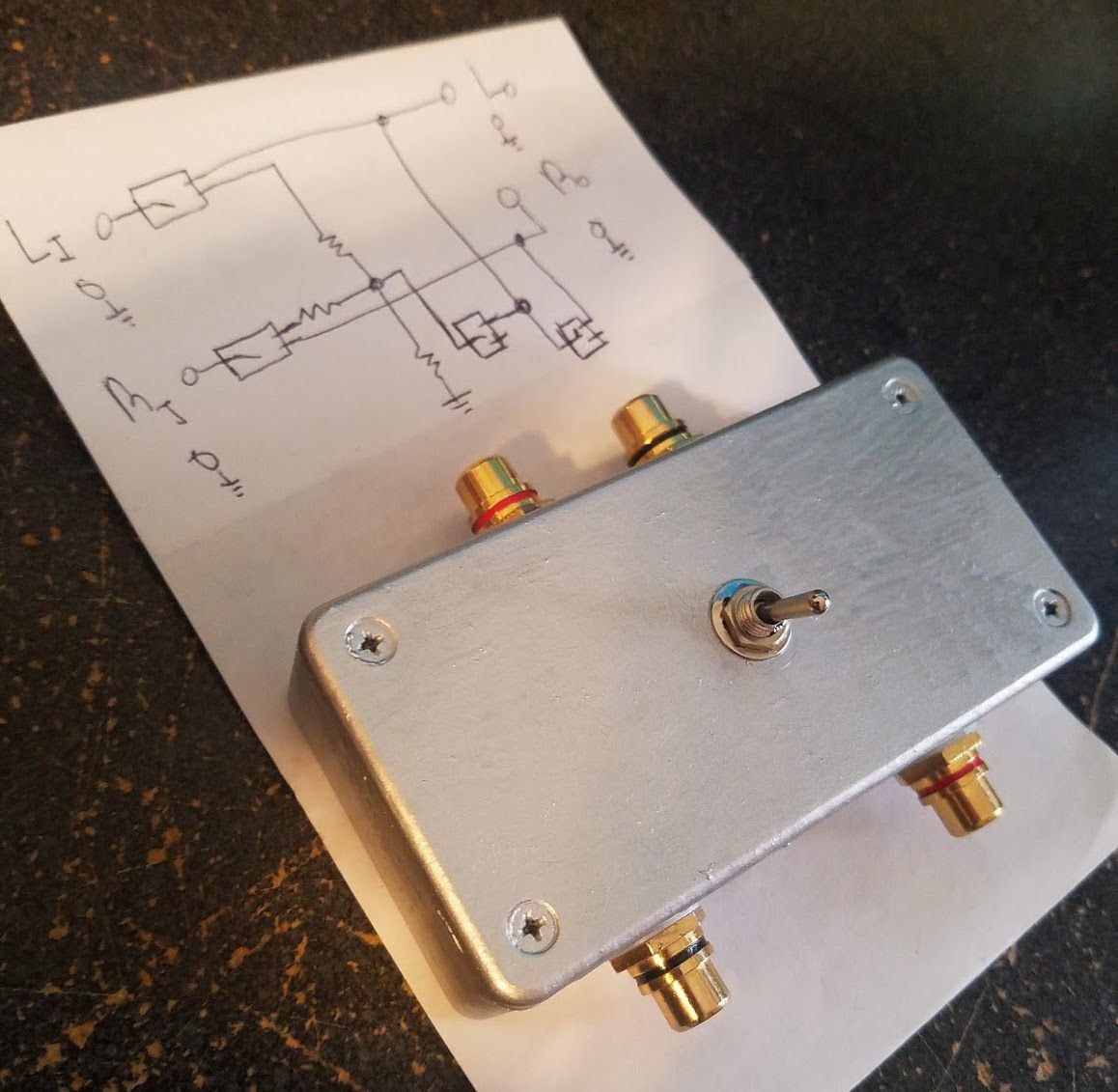
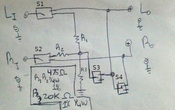
This circuit provides a good base, but a few modifications are needed. One is the use of standard RCA jacks for the left and right channels on the inputs and output. A potential version 2 could have both 3.5mm stereo jacks as well as RCA jacks. I will also add a 4PDT (4 position, dual throw) ON-ON switch. This will provide enough switching inputs and outputs to make it so when the switch is in the "Stereo" position the inputs are passed through directly to the outputs while also ensuring the outputs are completely disconnected and when the switch is in the "Mono" position the inputs will be passed through the resistors and the summed signal is passed to both output channels. The following circuit summarizes these additional features.
Parts & Tools
- 22AWG Wire (at least 2 colors, 3 is prefered)
- 2 - 475 Ohm 1% Tolerance 1/4W Resistor
- 1 - 20K Ohm 1% Tolerance 1/4W Resistor
- 1 - 4PDT switch
- 4 - RCA Jacks
- A Project Enclosure (ABS or Aluminum)
- Soldering Iron
- Solder
- Drill Bits (sized for the toggle switch and RCA jacks)
- Drill
- Ruler
- (Optional) Heat Shrink Tubing
- (Optional) 2 - 3.5mm TRS Jacks
Since this circuit is still rather simple we will not need a proto board and since the circuit is completely passive we do not have to worry about a power supply.
Construction
It's a good idea to use heat shrink tubing on the bare connections after you are soldering. Since this is optional, I will not be pointing out all the places to apply heat tubing. Make sure to measure, cut, and set lengths of tubing as needed whenever a bare joint is created. Start by measuring out some wire and solder the collar rings for the RCA grounds together. Now measure out 2 lengths of wire to solder to our first 2 switch inputs. These will be our left in and right in. On one side of these inputs solder 2 additional lengths of wire to the output pins. These will we our stereo pass through connections. On the opposite set of outputs solder in one end of the 475 Ohm resistors to each output. Afterwards join the other ends of the 475 Ohm resistors together, add one end of the 20K Ohm resistors, twist in a small length of wire to create the 4 way circuit from the diagram, and solder all 4 ends together. The other end of the 20K Ohm resistor can either be soldered to the ground wires now or done later, but don't forget to finish the connection. Take the other end of the small length of wire from the junction that was just created and solder it to one of the remaining inputs. Be vary careful with the next couple steps. Solder another wire to the output of this switch that is on the same "side" as the outputs the resistors were wired to. We want this switch to act as an On-Off switch rather than an On-On switch and we want it to be off when the switch is toggled to stereo mode. Solder 2 wires to the other end of the wire that was just soldered to the output of the 3rd switch. Solder 1 of these wires to the left or right positive outputs (its doesn't matter which once the signal has been summed) and solder the other to the 4th and last switch input on the 4PDT switch. Once again be very careful with the next step. Solder a wire to the output that will be on in mono mode and solder the other end of the wire to the remaining output jack. Solder the wires from the stereo pass through outputs on the switch to the RCA outputs. Make sure you do not mix up the left and right channels when wiring the stereo pass through. At this point the entire circuit should be wired up and the only steps remaining involve preparing and closing up the project box. Measure out and mark off the locations for the RCA input set, the RCA output set, and the toggle switch. Drill out the 5 holes in the project enclosure and then mount them with the provided nuts and washers. Close the enclosure up and you should now have a working switchable stereo-to-mono channel summing box. If you do end up also including 3.5mm jack input and outputs in addition to RCA jacks pay close attention to the wiring of the 3.5mm left and right channels since it is both easier to wire incorrectly and far hardier to correct afterwards. Also keep in mind that you cannot wire in 2 different inputs at the same time in you do include both input types.